Update: I have started a Patreon page to fund research projects which you can read about here – http://knifesteelnerds.com/how-you-can-help/
To harden steel you heat it up to high temperature to form a phase called austenite, followed by rapid quenching to make a very strong phase called martensite. Hardness is a measure of strength. I covered the process of austenite formation in the following post: Austenitizing Part 1. To summarize that post:
- Steel has multiple phases, just like how water can be a solid, liquid, or gas, steel can have different atomic arrangements, or “phases” while still being a solid. Two of these phases are called austenite and ferrite.
- Austenite has a relatively high solubility for carbon while ferrite can only contain a very small amount of carbon (<0.02%).
- Ferrite is magnetic and present at room temperature and the steel transforms to austenite at high temperatures which is non-magnetic.
When the steel is cooled slowly from the high temperature austenite phase, the carbon precipitates out so that the low carbon ferrite phase can form, leading to a soft, low hardness steel. The carbon precipitates out as carbides or pearlite which I will have to explain in more detail in a future article. However, if the steel is cooled rapidly the carbon doesn’t have sufficient time to precipitate out. As the austenite is cooled down the “driving force” or the degree the steel “wants” to transform to ferrite increases to the point where the steel wants so badly to transform to ferrite that it transforms to a new phase instead, a phase similar to ferrite but is saturated with carbon, and has a modified crystal structure to accommodate the carbon. Instead of the “body centered cubic” microstructure of ferrite, the unit cell is elongated, and called “body centered tetragonal” [1]:

Solid Solution Strengthening
The carbon atoms are much smaller than the iron atoms so they are present in between the iron atoms, which is called an “interstitial” atom. These carbon atoms strain the bonds of the iron atoms which strengthens the material. Here is a handy schematic to better understand the strain on the atomic lattice (thanks Wikipedia) [2]:
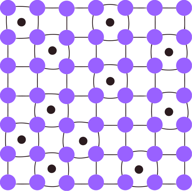
The change in strength through the presence of other (non-iron) atoms is called “solid solution strengthening.” Carbon has a strong contribution to solid solution strengthening of ferrite and martensite behaves somewhat similarly [3]:

The strain in the lattice increases strength by affecting the movement of dislocations, which are line defects in the crystal structure that control strength of materials. I introduced them and described how they affect strength in the following article: How Does Grain Refinement Lead to Improved Properties? A couple important things to keep in mind from that article are the following:
- The more difficult it is for dislocations to move, the higher the strength/hardness of the material.
- Dislocations cannot easily pass through themselves, so if there is a sufficient number of them then they cannot easily move. A high “dislocation density” leads to high strength/hardness.
- There are different boundaries within steel such as grain boundaries that act as barriers to dislocation movement. More boundaries means higher strength/hardness.
- Dislocations move along “slip planes” which are usually the most densely packed planes of atoms.
Martensite Transformation
When martensite forms it is a “diffusionless” transformation. With normal transformations such as slow cooling to form ferrite the atoms have to diffuse to form the new phase. With martensite formation, however, the steel is rapidly quenched and does not have time for long-range diffusion of atoms. Instead, the atoms make a small “shift” in tandem to form the new martensite microstructure, which is called a “shear transformation.” For a simplified schematic that shows this change look at the following [4]:
You see the martensite transformation in action in this awesome video of a low carbon steel using a technique called laser confocal microscopy [5]:
You can see that the martensite “laths” appear almost instantly, and in fact approach the speed of sound. The transformation is diffusionless, remember, and is not reliant on time, but only temperature. If the steel is held at a temperature where 90% martensite has formed, it will remain there unless the steel is further cooled. The other 10% will still be austenite, which is called “retained austenite.” Therefore, the degree of martensite formation is controlled by temperature [6]:
![]()
The laths start, or “nucleate” at one austenite grain boundary and travels until it reaches either a boundary on the other side of the grain or another martensite lath. They nucleate at grain boundaries because those are high energy areas that are preferential for the nucleation of new phases. They end at another boundary because the transformation occurs through the diffusionless shear transformation of atoms. The boundaries are the point at which a different orientation of atoms is present, as described in the grain refinement article I linked to earlier. With a whole different orientation of atomic planes, the martensite cannot form through a short shift in the atoms, so the lath ends at the boundaries where the crystal structure changes direction, as shown in this high resolution transmission electron microscope image of a grain boundary [7]:
Dislocation Strengthening
When the shear transformation occurs a large density of dislocations is created to accommodate the strain created by the shift in atoms. As described earlier, a high density of dislocations leads to higher strength/hardness. Increased carbon in the martensite leads to a higher dislocation density which is in part where the higher strength of martensite comes from [8]:
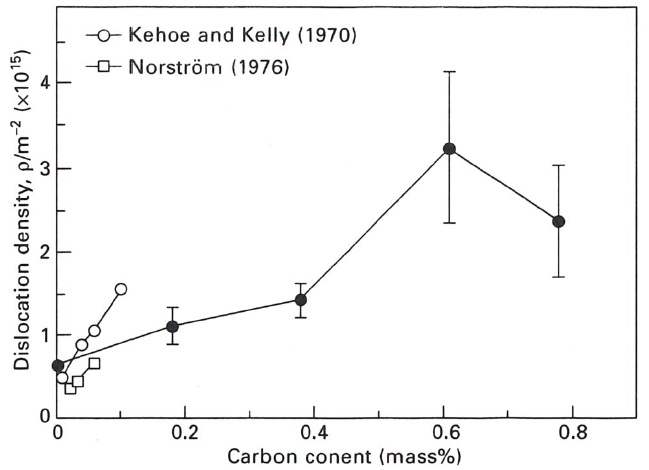
You can also see that there is a drop in dislocation density from 0.6 to 0.8% which is the transition between “lath” and “plate” martensite. Plate martensite forms by a twinning mechanism instead which I won’t be getting into in this article. For simplicity’s sake, we will stick with the general conclusion that higher carbon leads to higher dislocation density which means the dislocations do not move as readily leading to higher strength/hardness.
Boundary Strengthening
Grain boundaries are not the only boundaries that impede dislocation motion thereby increasing strength. Within martensite there are “packet” and “block” boundaries that also act to impede the movement of dislocations [9][10][11]:
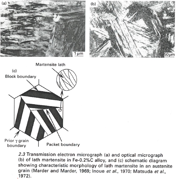
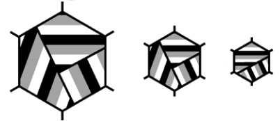
If you watch the Youtube video I linked earlier in this article you may also be able to see the packets and blocks. A packet or block is a group of parallel laths, and the distinction between the two requires too much writing to cover here (same habit plane for packets and same orientation for blocks). Because the low-angle boundaries of packets and blocks also act to impede the motion of dislocations, the size of the packets or blocks is sometimes called the “effective” grain size of martensite. The size of the packets/blocks is reduced by decreasing the grain size, as is illustrated in this schematic [12]:
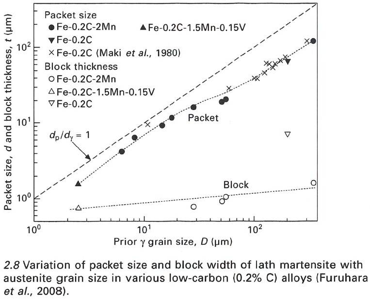
The size of the packets and blocks controls strength in a similar manner to grain size, which is why it is sometimes called the “effective” grain size. It makes a very similar plot to grain size vs strength, as was described in the grain refinement article that I will keep linking to until you actually click on it and read it. Here is a plot showing the correlation between grain size and packet and block size [12]:
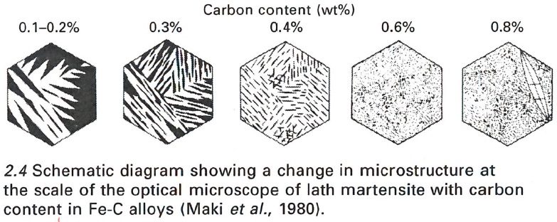
Another important factor that controls the size of the packets and blocks in carbon content; the higher the carbon content the smaller the packets and blocks. This is another mechanism by which higher carbon leads to stronger martensite [13][14]:
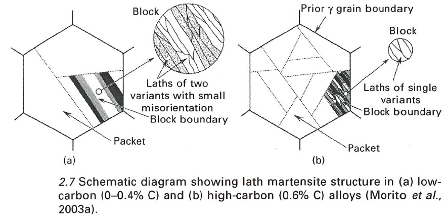
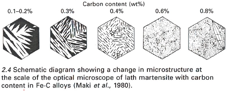
You can see in the schematic how the packets, blocks, and laths are decreased in size with increasing carbon content. You can also see in the 0.8%C steel that a “plate” of martensite was formed, which I described in the dislocation density section. Higher carbon leads to a shift between laths and plates [15]:

Martensite plates are generally not desirable because the toughness of plate martensite is lower than lath martensite, in part because of “microcracks” that are formed in plate martensite [16]:

Slip Planes
The type of crystal structure a material has controls the number of “slip planes” along which dislocation slip occurs. You might remember from the Effect of Grain Size article that you have definitely read by now that dislocation motion preferentially occurs along close-packed planes of atoms [17]:
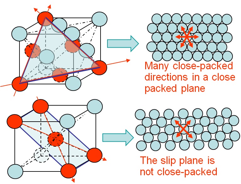
The Body Centered Tetragonal (BCT) has a low number of slip planes available for dislocation motion so the microstructure itself makes dislocation movement more difficult. Higher carbon leads to more “tetragonality” of the microstructure.
Summary and Conclusions
Martensite gains its high strength through several mechanisms. It is not entirely known which of the mechanisms are the most important, but I covered several of the major ones:
- Solid solution strengthening from the high carbon content, leading to strains in the atomic lattice that impede dislocation motion.
- High dislocation density created from the shear transformation.
- High density of boundaries through the formation of packet and block boundaries.
- Low number of slip planes available for dislocation motion in BCT.
These mechanisms combine together to make the very strong/hard martensite that we know and love; all of the mechanisms are increased by carbon content, and indeed we find that the strength of martensite is greatly controlled by carbon content [18]:

What this Means for Making Knives
There is a lot of technical information in this article to better understand how the martensite transformation works and how it makes steel hard and strong. Some of this detail is more than is necessary to know how to make a knife. The bottom line is that quenching steel from high temperature makes it hard, the transformation to martensite makes it hard, and more carbon in the martensite makes it harder. This information should contribute to your understanding when reading other articles on heat treating such as what I wrote in Austenitizing Parts 1, 2, and 3. The details of martensite also allows me to write about the process of tempering now since anyone who has read this article understands how carbon is present in martensite, what “tetragonality” is, the dislocation density of martensite, and therefore I can describe how all of these things are modified during tempering.
Bonus! Why is Martensite Tetragonal?
A question you may have asked yourself is this: why is martensite body centered tetragonal (elongated cube) rather than just a bigger cube? Why is the carbon preferentially located in one direction? Well I’m glad you asked, dear reader. We have to go back to the face centered cubic microstructure of the high temperature austenite, which has interstitial carbon atoms between its iron-iron bonds [19]:
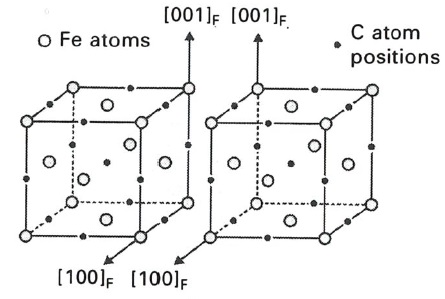
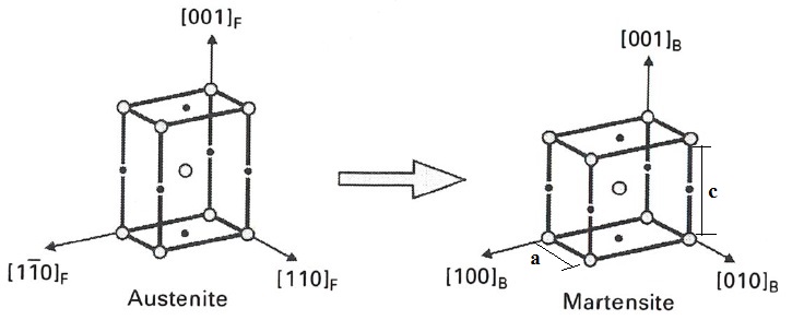
There are two unit cells of austenite shown for a reason, because when you stick two of them together, you can find a unit cell that looks very much like body centered cubic ferrite, as is shown by the dark lines in this schematic [19]:
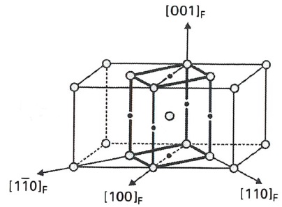
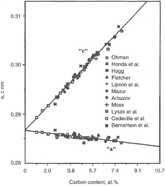
You can see that there are carbon atoms located on the “vertical” lines between iron atoms, but none located between the iron atoms in the sides of the square on top and bottom. This leads to a preferential increase in the vertical, or “c” direction, with a shrinking in the horizontal, or “a” direction, and therefore the degree of “tetragonality” is increased with higher carbon content [19][20]:
[1] Adapted from http://www.seas.upenn.edu/~chem101/sschem/solidstatechem.html
[2] https://en.wikipedia.org/wiki/Strengthening_mechanisms_of_materials
[3] Pickering, F. B. “Microalloying 75.” Union Carbide Corp., New York, NY 9 (1977).
[4] https://www.tf.uni-kiel.de/matwis/amat/mw1_ge/kap_8/backbone/r8_4_1.html
[5] https://www.youtube.com/watch?v=OQ5lVjYssko
[6] http://labs.mete.metu.edu.tr/sma/smatext/MART.htm
[7] https://www.tf.uni-kiel.de/matwis/amat/iss/kap_5/backbone/r5_3_1.html
[8] Morito, S., J. Nishikawa, and T. Maki. “Dislocation density within lath martensite in Fe-C and Fe-Ni alloys.” ISIJ international 43.9 (2003): 1475-1477.
[9] Marder, J. M. “The morphology of iron-nickel massive martensite.” Trans. ASM 62 (1969): 1-10.
[10] Inoue, Tohru, Shôichi Matsuda, Yoshihiro Okamura, and Kôichi Aoki. “The fracture of a low carbon tempered martensite.” Transactions of the Japan Institute of Metals 11, no. 1 (1970): 36-43.
[11] Matsuda, S., T. Inoue, H. Mimura, and Y. Okamura. “Toughness and Effective Grain Size in Heat Treated Low-Alloy High-Strength Steels.” Trans. Iron Steel Inst. Jap. 12, no. 5 (1972): 325-333.
[12] Furuhara, T., K. Kikumoto, H. Saito, T. Sekine, T. Ogawa, S. Morito, and T. Maki. “Phase transformation from fine-grained austenite.” ISIJ international 48, no. 8 (2008): 1038-1045.
[13] Morito, S., H. Tanaka, R. Konishi, T. Furuhara, and and T. Maki. “The morphology and crystallography of lath martensite in Fe-C alloys.” Acta Materialia 51, no. 6 (2003): 1789-1799.
[14] Maki, Tadashi. “The Morphology of Microstructure Composed of Lath Martensite.” Trans ISIJ 20 (1980): 207-214.
[15] Marder, A. R. “The morphology of martensite in iron-carbon alloys.” Trans. ASM 60 (1967): 651-660.
[16] Marder, A. R., A. O. Benscoter, and G. Krauss. “Microcracking sensitivity in Fe-C plate martensite.” Metallurgical Transactions 1, no. 6 (1970): 1545-1549.
[17] http://www.ltas-cm3.ulg.ac.be/FractureMechanics/overview_P3.html
[18] Krauss, George. “Martensitic transformation, structure and properties in hardenable steels.” Metallurgical Society AIME,(1978): 229-248.
[19] Bain, Edgar C., and N. Y. Dunkirk. “The nature of martensite.” trans. AIME 70, no. 1 (1924): 25-47.
[20] Cheng, Liu, A. Böttger, Th H. De Keijser, and E. J. Mittemeijer. “Lattice parameters of iron-carbon and iron-nitrogen martensites and austenites.” Scripta metallurgica et materialia24, no. 3 (1990): 509-514.
Nice article. Thought you might like this paper. https://www.phase-trans.msm.cam.ac.uk/2004/Tempered.Martensite/tempered.martensite.html Will you post an article talking about why tempering decreases how brittle the steel is? I imagine it’s something to do with the retained austenite forming planes of weakness for fractures to develop along and tempering converts the retained austenite to martensite? Keep up the good work.
I will definitely be writing an article about tempering sometime in the not-too-distant future.
So hardness increases with carbon dissolved in BCC tetragonal iron, not the amount of carbon in the steel? Or does it once again harden more once you get to plate martensite only? And if so do we just get more easily hardening steels when the carbon content is above 0.6% because there is more carbon around to make sure the bcc iron is filled and the carbide formers are not too bare… so if we compare similar alloys one with 0.63% and the other with 0.73% carbon it will just be easier to get the higher carbon up to say 65rc as quenched… provided you dont overdo carbon in solution?
The carbon has to be present within the martensite to increase its hardness. If the carbon is present as cementite or other carbides then it will not increase the hardness of the martensite. “Overdoing” carbon in solution does not reduced hardness unless large amounts of retained austenite are formed. Plate martensite is not softer than lath martensite.
So why the decrease in hardness noted by the experiment? And why is 0.67% C often touted as the max amount of elemental c dissolved in iron? And how does this relate to the comment that plate martensite is weaker than lath martensite and the combo between lath and plate martensite is also considered weaker because ithe boundary between lath and plate often thought to be weaker?
There was a drop in dislocation density but not in hardness. See the figure near the bottom of the article that shows hardness vs carbon content. Hardness does start to plateau around 0.6%C or so. I’m not sure what the 0.67%C number is that you are referring to. You might mean 0.77%C which is the approximate eutectoid carbon content. But you can have more carbon in austenite than that, as I described in Austenitizing Part 1: http://knifesteelnerds.com/2018/02/28/austenitizing-part-1-what-it-is/
Will reread both articles
Hi,
when the apex is overheated during sharpening, and loses a few points HRC, how does that happen? the martensite is converted back to austenite? something else?
https://knifesteelnerds.com/2019/04/08/does-sharpening-with-a-grinder-ruin-your-edge/
Hi,
Are there any easier posts related to this one for me to start with? This is a bit too hard for me as I am still a high school student in UK.
https://knifesteelnerds.com/2019/07/01/what-a-good-heat-treatment-can-and-cannot-do/
On that hardness vs carbon content figure, do you know if these were quenched to room temperature or below? Does the hardness keep going up with carbon concentration if you use cryo, the way cryo boosts the peak hardness in stainless/alloy steels?
Some of them used liquid nitrogen and some didn’t which is why some showed a drop and some a small increase at the top end.