Thanks to Warren Krywko, Joseph Cannell, and Timothy Thomas for becoming Knife Steel Nerds Patreon supporters! Your contributions will help fund more research on knife steels.
To discuss chipping we have to start with fracture mechanics of materials, and in this case steel. Chipping itself is just fracture, so by definition resistance to chipping is controlled by toughness. Unfortunately there are many definitions of toughness. I covered one definition of toughness in the article on spider silk, which is the area underneath the stress-strain curve:
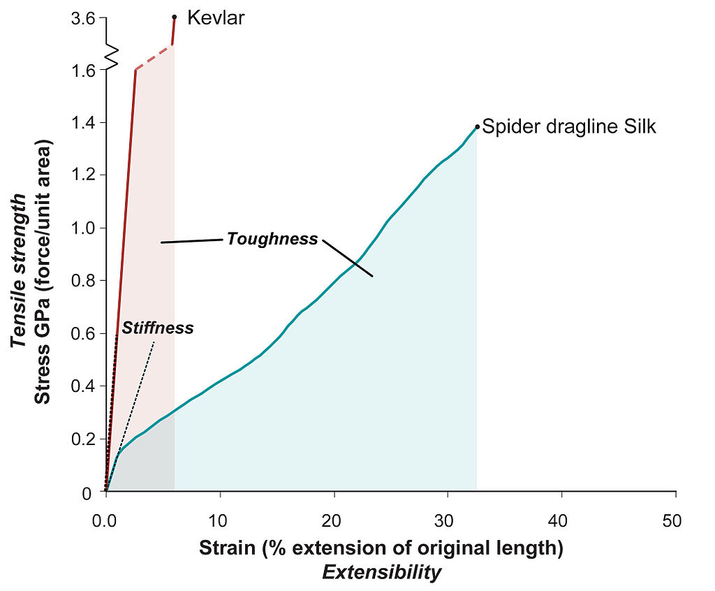
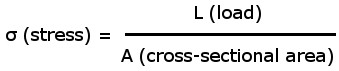
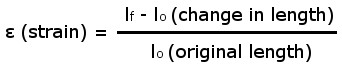
There is a brief intro to tensile testing in the article on flexing and bending. In the tensile test a material is pulled until it fractures. The stress (σ) is the load divided by the cross section, and strain is the change in length divided by the original length. Therefore, stress and strain are normalizing terms that are affected by the size of a specimen. A load applied to a small sample results in a larger stress than the same load on a large sample. With the definition of toughness given by the area underneath the stress-strain curve, greater values of toughness are given by stronger materials (high stress) with high ductility (high strain).
Fracture Toughness
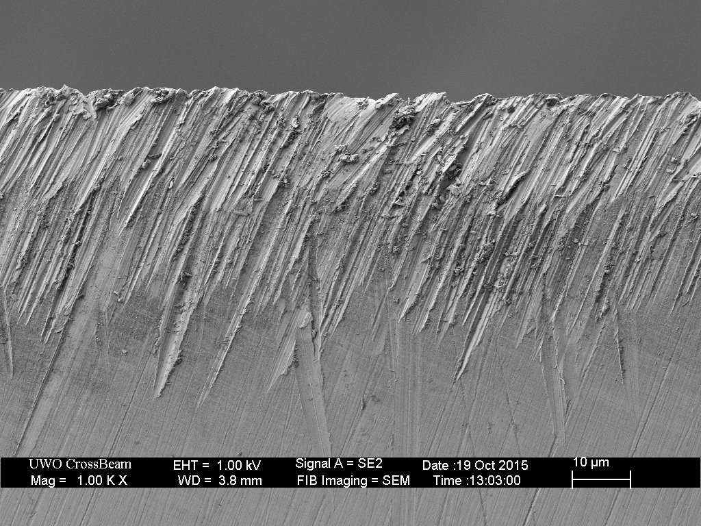
An important measure of toughness is the resistance to fracture in the presence of a pre-existing crack. This is important because most parts in service have some level of imperfection to them. For example, a knife edge sharpened to rougher finishes will have larger scratches than a finely sharpened edge, and these scratches can be thought of as pre-existing flaws [1]:
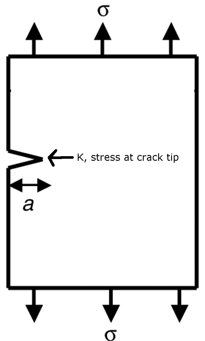
Fracture is measured in terms of K, or “stress-intensity factor” which is the stress at the crack tip. K is proportional to the stress and the square root of the size of the flaw. Therefore a larger flaw means that less stress is required to cause fracture:
![]()
Using specimens designed for testing fracture toughness you then get a test that looks something like this where the stress required for crack propagation can be measured by pulling apart the specimen:
Another method for measuring crack propagation is with a three-point or four-point test such as this one where they measure the fracture toughness of watermelon, because science is important:
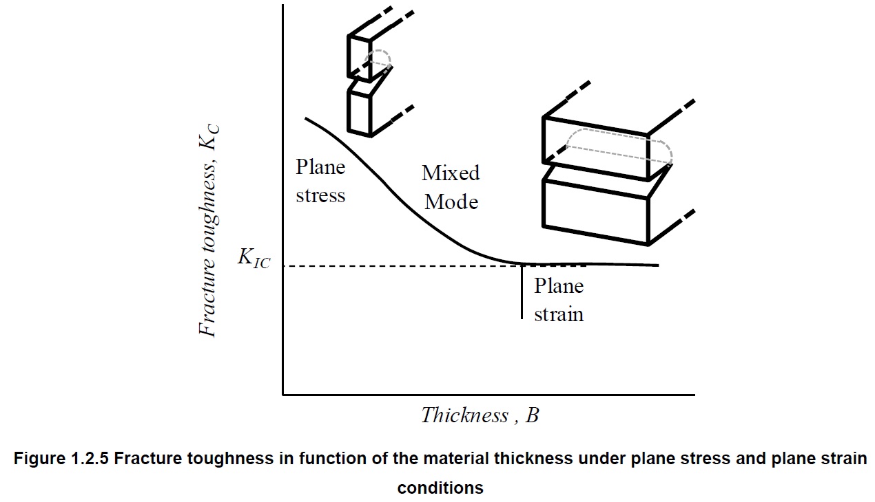
Fracture toughness is measured in dimensions of MPa*√m (stress*√length). An important reported toughness value is KIC, or plane strain fracture toughness, which is a material property for pulling apart fractures (no twisting or shearing) using specimens that are sufficiently thick that the value is no longer affected by thickness:
Crack Initiation and Fatigue
If the flaw or crack size is sufficiently small then the material will yield (deform) first rather than fail rapidly by fracture. Therefore, a sufficiently large crack must form first before crack propagation can occur. Crack initiation occurs due to different mechanisms than crack propagation. Because fracture toughness testing is performed with pre-cracked specimens the effect of crack initiation is not included.
Charpy Impact Testing
Impact testing is performed by dropping a heavy weight on a pendulum through a sample and measuring the degree that the sample resisted fracturing. If there was no sample present the weight would reach the same height on the other side. The more resistant the sample is to fracture the lower the height is that the weight reaches on the other side. Charpy impact samples are often “notched” so that fracture occurs in a consistent region and has lower variability [2]:
Fracture Toughness vs Charpy Toughness
The two major differences between charpy toughness and fracture toughness are 1) charpy testing is dynamic (falling pendulum breaks sample) rather than static (specimens slowly pulled apart) and 2) fracture toughness is performed on pre-cracked samples while charpy samples are typically not pre-cracked. Charpy toughness testing cannot generate a “material property” in the same way that fracture toughness can because the values are always affected by sample size. Therefore, “serious” fracture analysis is typically performed with fracture toughness testing. Fracture toughness is usually more expensive than charpy impact testing, however, and even with these differences charpy v-notch testing and fracture toughness results are often highly correlated [3][4]:
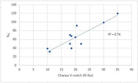
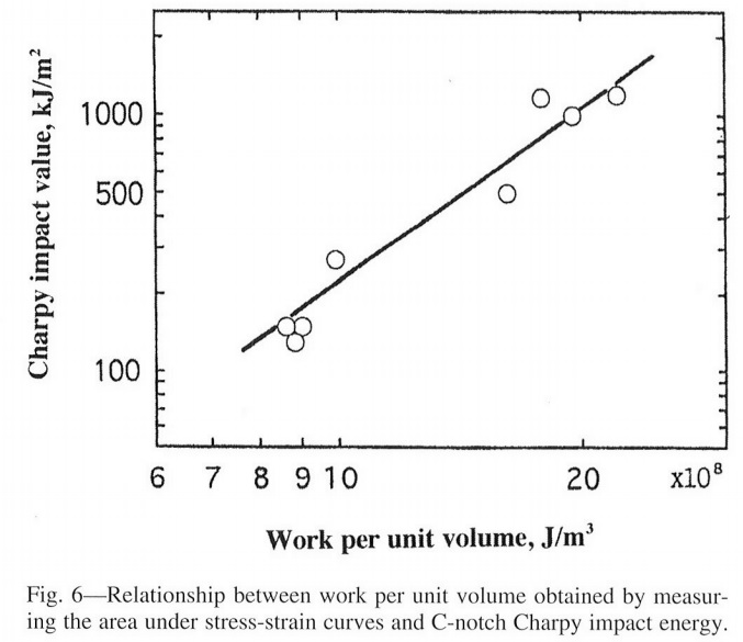
One of the reasons that charpy v-notch and fracture toughness are highly correlated is because the presence of the notch in the charpy specimen greatly reduces the energy required for crack initiation. However, in the case of unnotched samples the situation is somewhat different because there is no stress riser for lowering the energy required for crack initiation. This makes unnotched testing somewhat more variable because the crack can initiate anywhere over a certain distance because there is no notch. However, this also means that the effect of crack initiation on fracture is better captured by unnotched specimens, or gentle notches like c-notch or u-notch. Because unnotched or c-notch charpy testing incorporates both crack initiation and propagation, it correlates much more strongly with the area under a tensile curve [5]:
Fatigue Initiated Fracture
Chipping and micro-chipping does not have to occur with a single impact, but can happen by the material being stressed multiple times:

The damage to a material due to repeated loading is called fatigue. A three-point bend fatigue test can be seen in the following video:
The higher the stress applied, the smaller the number of cycles a sample can withstand prior to fracture. With sufficiently low applied stress the material will never fracture (at least with martensitic and ferritic steel), and this stress level is known as the “fatigue limit” or “endurance limit” [6]:
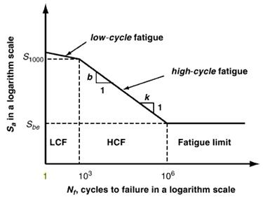
Below a certain number of cycles, the material reaches a region of “low-cycle” fatigue (high stress) rather than “high-cycle” fatigue (low stress), usually the cutoff point is given as 1000 or 10000 cycles, so failures in knives are almost always in the low-cycle fatigue regime. Typically low-cycle fatigue is at sufficiently high stress levels where small amounts of yielding (permanent deformation) occurs. Micro-chipping and chipping of edges occurs in the low-cycle fatigue region [7]. Low-cycle fatigue is more greatly controlled by toughness and less by the slow crack growth dominated by high-cycle fatigue [8]. This can be understood through analysis of the effect of ΔK on crack growth [7]:
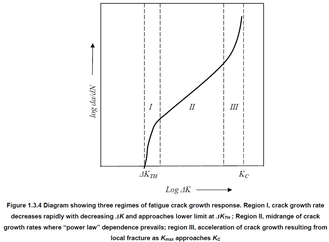
This plot shows the crack growth rate on the y-axis and ΔK on the x-axis. ΔK is the difference in stress intensity factor, K, during loading and unloading (leading to fatigue), ΔK = Kmax – Kmin. So if a sample is loaded to a certain stress and then unloaded it would be ΔK = Kmax – 0 = Kmax. As described earlier, higher stress would mean a higher K value and a larger crack would mean a higher K value. At sufficiently small stress there is no growth of cracks, but above ΔKTH the cracks grow. Region I is slow crack growth, but the rate of growth increases with higher ΔK. Region II shows the region with moderate crack growth rates that are consistent over a relatively wide range of ΔK values. Region III is characterized by more rapid crack growth, and with sufficiently high ΔK then the piece breaks in one cycle and is therefore equal to or greater than the fracture toughness, KC. With sufficiently high stress applied a sample can jump into Region III or even to KC, but K is also controlled by crack size. Therefore, even with a fixed stress applied the ΔK can grow because the crack is growing, meaning that a sample can move through all three regions shown in the plot. Region III can describe low-cycle fatigue as it has a high stress-intensity factor on a crack tip. The higher the stress the closer the behavior is to fracture toughness, KC. Therefore because chipping and micro-chipping is controlled by low-cycle fatigue, we would expect toughness to have a strong effect on chipping of knife edges.
Fatiguing of materials in practice
While testing in the laboratory usually uses a constant stress or strain, use of knives is by humans, and humans do not apply constant stresses, so the pattern might look more like this:
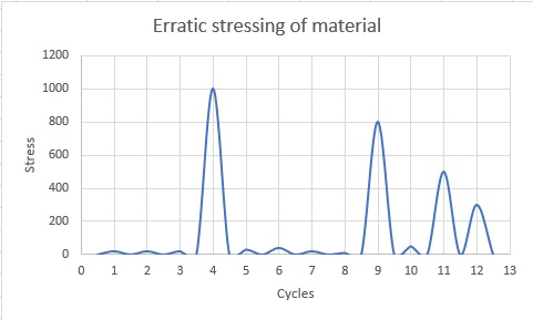
In this case the damage to the material is cumulative; the application of a low number of large stresses reduces the number of smaller stress cycles that the material can withstand.
Crack Initiation
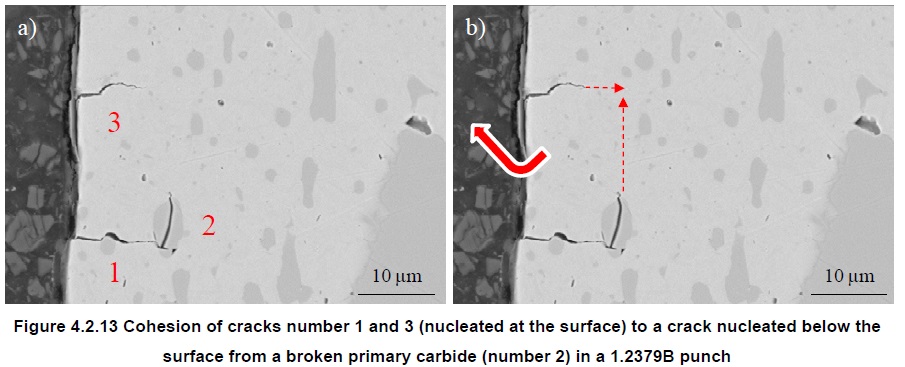
While crack initiation can certainly occur at previous flaws, in the absence of sufficient flaws they occur at microstructural features instead. With steels used in knives there is usually some amount of hard, brittle particles called carbides that contribute to wear resistance. Often large carbides are present where cracks form, either at the interface between steel and carbide or cracking of the carbides themselves [9]:
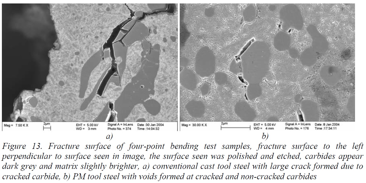
Larger carbides require less applied stress to crack than smaller carbides. In a comparison between conventionally cast 1.2379 (D2) steel and a powder metallurgy steel HWS it was found that the stress required for crack initiation was vastly different (note difference in magnification) [7]:
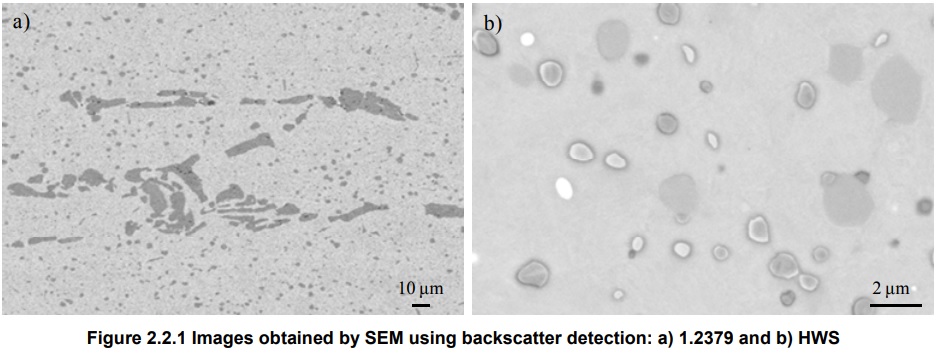
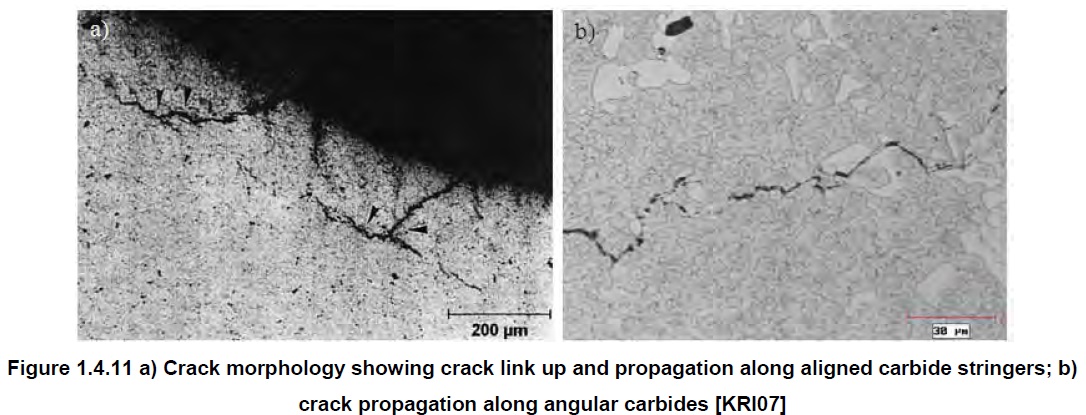
The stress required for cracking of carbides in the D2 was found to be only 700-900 MPa, while steels with smaller carbides required higher stress levels to crack the carbides. The cracking of these carbides is particularly bad because the cracks can easily grow along segregated carbide bands [7]:
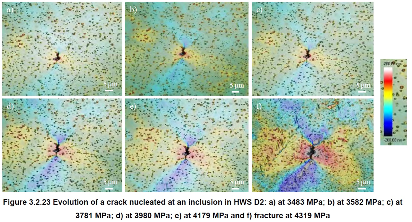
However, cracking of carbides was not seen in the HWS powder metallurgy steel, but instead the cracks initiated at impurities because they were larger than the carbides, and therefore the stress required for cracking at impurities was lower than for carbides. The stress required for crack initiation was still much higher than that required for D2, however, on the order of 3400-3600 MPa [7]:
Crack Initiation vs Fracture Toughness
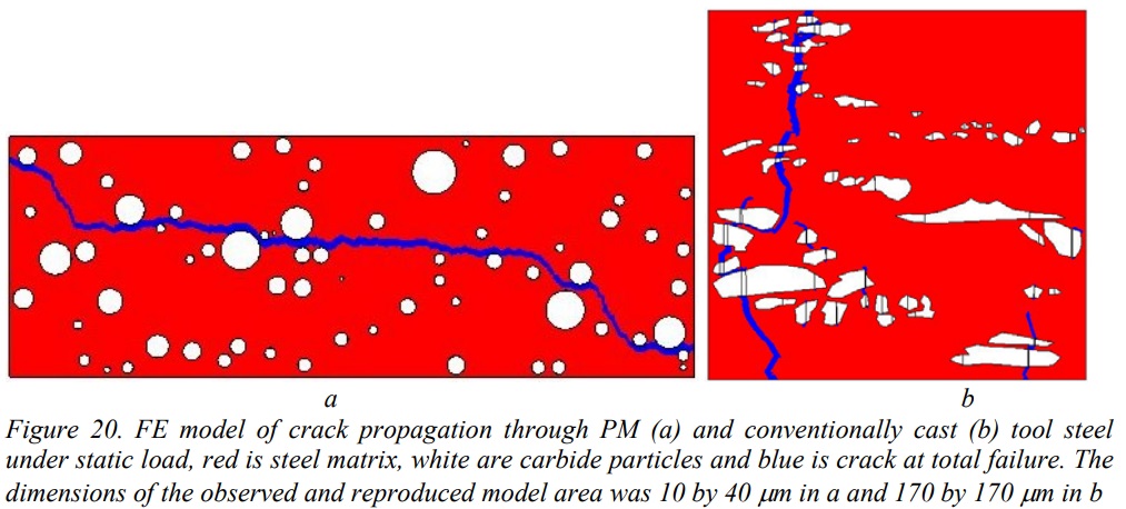
One interesting thing found in the study comparing D2 and HWS was that the fracture toughness of HWS was actually lower than D2. HWS had fracture toughness of 20 MPa*√m while for D2 it ranged from 22-28 MPa*√m depending on orientation. The researchers reported that because the carbides are so small and evenly distributed in the powder metallurgy steel that they are, on average, closer together than for D2. Therefore a pre-existing crack can more easily grow throughout the steel by jumping from carbide to carbide [9]:
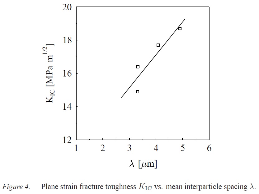
In testing of shearing dies operated by trimming of high strength sheet steel, it was found that the HWS PM steel did not have superior fracture resistance to D2 steel when in the presence of large initiated cracks, and they attributed this to the ease in crack propagation of the PM steel despite its resistance to crack initiation. Another conventionally cast steel with a lower carbide volume, however, showed superior resistance to fracture due to its higher fracture toughness from a small carbide volume combined with a relatively large average distance between carbides. In the presence of small cracks which lead to micro-chipping, superior behavior was found in the PM steel. Therefore, the type of loading and use of a knife edge is important in determining which steel will show superior behavior. They concluded that the PM steel was better for short cracks and high stresses while the D2 was better at resisting crack propagation of large cracks. Similar results were found in a comparison of four different PM steels with similar carbide volume but different carbide size distributions. The PM steel with the largest carbides and highest hardness was found to have the best fracture toughness because the distance between carbides was greatest [10]:
Surface wear and machining grooves
In the study comparing HWS and D2 in shearing dies it was found that both wear and fatigue occurred in the steel. They found that the wear of the dies led to lower stress required for crack initiation which is part of what increased the chance for fracture in the PM steel they tested. It was also discovered that grooves left over from machining led to much lower stresses required for crack initiation. They recommended that PM steels be used either when smooth surfaces can be guaranteed or with coatings applied to limit crack initiation. This was confirmed in another study on Vanadis 6 where a milled surface was found to lead to fracture without any plastic deformation [11]. In the case of poor finish quality the superior resistance to crack initiation doesn’t matter because the fracture toughness of PM and conventional steels is similar.
Effect of carbide volume on low-cycle fatigue
In a study comparing D2 (SKD11) with a modified steel with lower carbon and chromium for lower carbide volume and smaller carbides (M-SKD11), they found that with low-cycle fatigue the stresses allowed were much higher with the lower carbide volume steel:
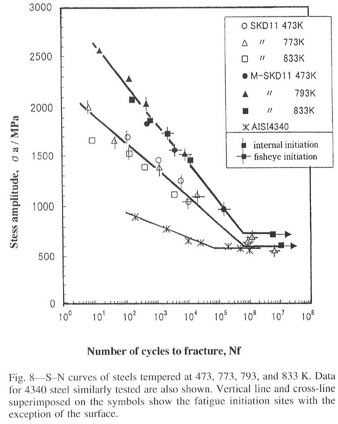
The D2 steel had 13.5% carbide volume, and a maximum carbide diameter of 21.5 microns, while the modified steel had only 4.5% carbide volume with a maximum carbide diameter of 14.4 microns. There is also a comparison point with 4340 steel, which would be expected to have significantly lower carbide volume than either, but because of its lower strength (correlated with hardness) it cannot withstand the same degree of stress. At high stress levels the researchers found that cracks initiated at the surface with large carbides at the origin of the fracture. The stress level required for surface initiation in D2 was 1100 MPa, but for the modified steel was 1800 MPa. This is why when loaded to a similar stress level the modified steel with less carbide and smaller carbides lasts for 1-2 orders of magnitude more cycles than D2. The difference is greatest for a small number of cycles and high stresses which is the region of interest for knives when it comes to chipping resistance.
Effect of carbide volume and Hardness on Fracture Toughness and Impact Toughness
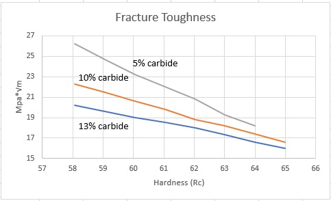
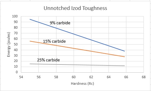
Higher carbide volume has also been found to lead to lower fracture toughness and lower impact toughness as measured by charpy or izod. Therefore a lower carbide volume improves resistance to both crack initiation and crack propagation. Higher hardness also reduces both fracture and impact toughness, and the effect of carbide volume becomes smaller at high hardness [12][13]:
Effect of Grain Size
I wrote an article about the effect of grain size on toughness: How Does Grain Refinement Lead to Improved Properties?
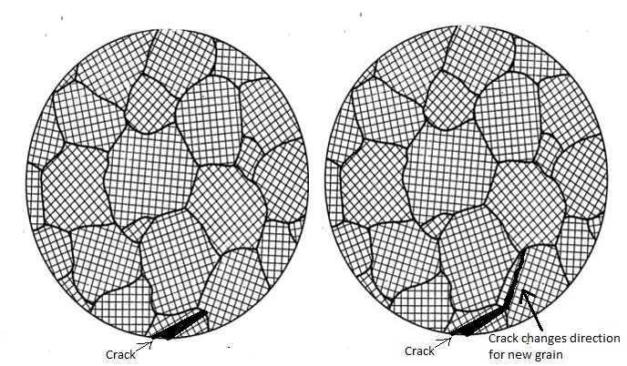
To summarize that article, smaller grain size means that a growing crack must re-initiate and change direction as it meets grain boundaries. Therefore a smaller grain size means higher toughness:
I also showed some examples of toughness numbers with different grain size in articles on austenitizing, particularly Part 2 and Part 3. Here is a chart I shared in Part 2:

Effect of Retained Austenite
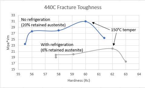
It is very common for custom knifemakers to use cryogenic processing of their steels which eliminates most of the retained austenite in the steel. I wrote a forum post about what retained austenite is and what cryo treatments do. Toughness testing usually shows an increase in toughness with greater retained austenite, as can be seen in this figure for 440C [5]:
However the concern sometimes is that through stressing of the steel with retained austenite present that the austenite will transform to (untempered) martensite and therefore the brittle phase will act to reduce toughness. However, fatigue testing of material paints a different picture, where the retained austenite containing steel, which converts to martensite during cyclic loading, has higher resistance to fracture [5]:
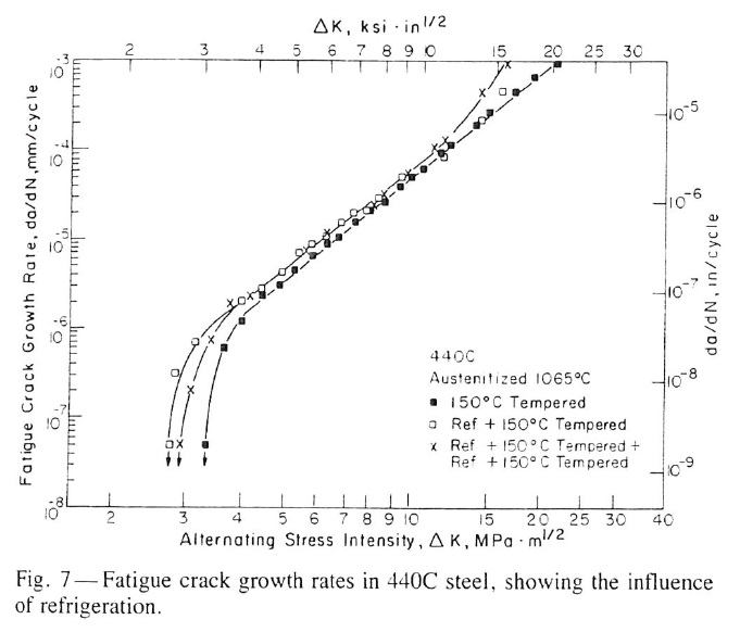
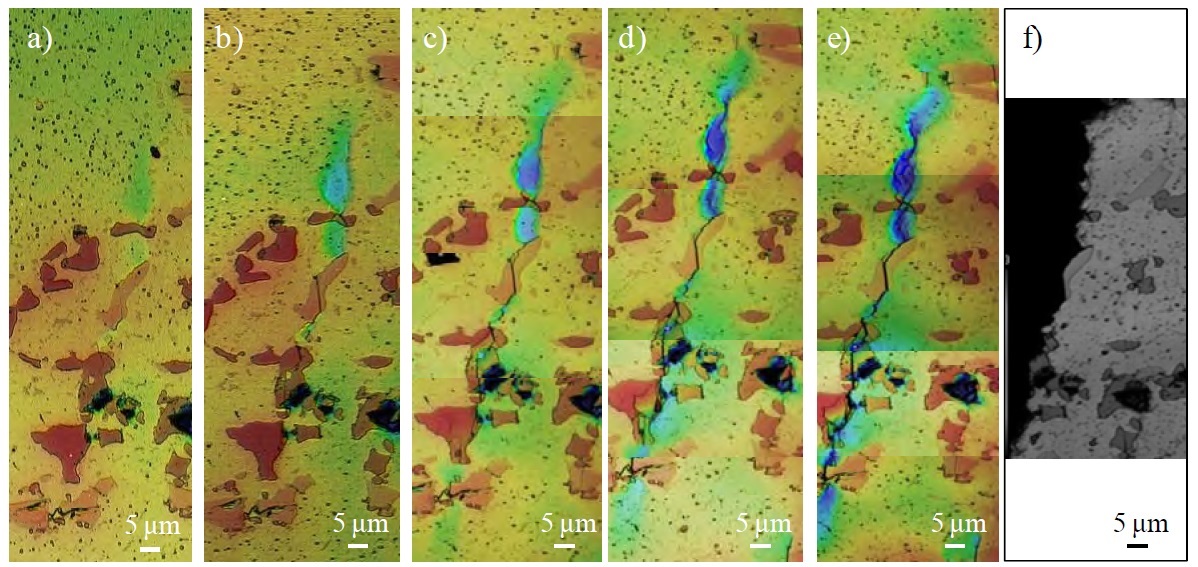
From that figure it can be seen that the steel with retained austenite had both a higher ΔKTH (stress intensity required for crack growth), and at high ΔK approaching KC (low-cycle fatigue and fracture toughness) the resistance to fatigue is better. The behavior in the steady crack growth region is similar between the two. During crack growth there is stress on the surrounding austenite and it transforms to martensite. Martensite is a larger phase (less dense) than austenite and therefore during the transformation the expansion from the transformation leads to “plasticity-induced crack closure.” A stress applied to the crack closes it and therefore the stress required for crack propagation is greater. A micrograph showing a crack growing within a ferrite (red)-austenite (green) microstructure is shown below, where transformation of the austenite to martensite can be seen around the crack (green austenite becomes black martensite) [14]:

Importance of Orientation
Steel is typically rolled to the final thickness, and carbides and impurities are oriented along the rolling direction. This leads to segregation of carbides in “stringers” that can be preferential bands for crack formation [15]:
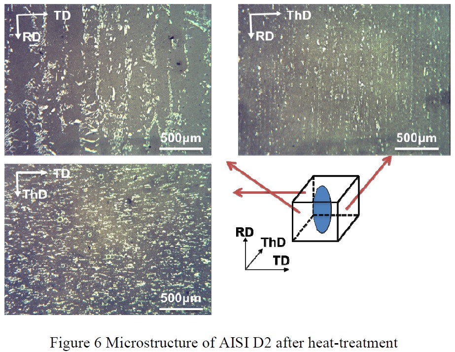
“RD” is the rolling direction, “TD” is the transverse direction (perpendicular to the rolling direction), and ThD is the thickness direction. With the aligned segregated carbides, it matters which orientation a toughness test is performed:
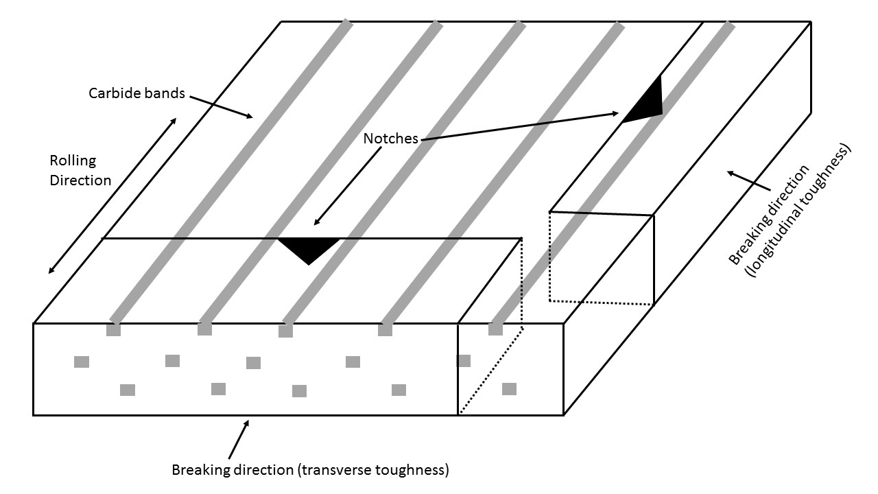
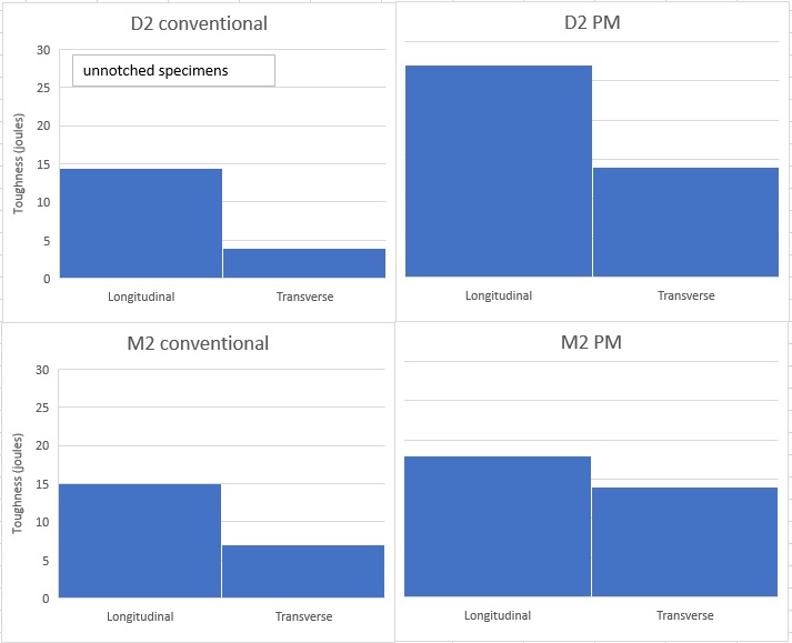
With the transverse toughness specimen the notch and the breaking direction are aligned with the segregated carbide bands. Therefore the crack can grow along those bands of carbides and the toughness with transverse specimens is lower when compared with longitudinal specimens. Powder metallurgy helps to reduce carbide segregation and therefore improve transverse toughness but has a smaller effect on longitudinal toughness [16]:
The direction of loading of edges has been found to have an effect on their fracture. Generally knives are oriented along the rolling direction so that the carbide bands are parallel to the edge:

Therefore side loading requires less stress to fracture the edges and chipping can occur along the carbide bands [15]:
If the knives are oriented along the transverse direction instead, then the tips of the blades would fail more easily in a similar fashion:

Micro-Chipping
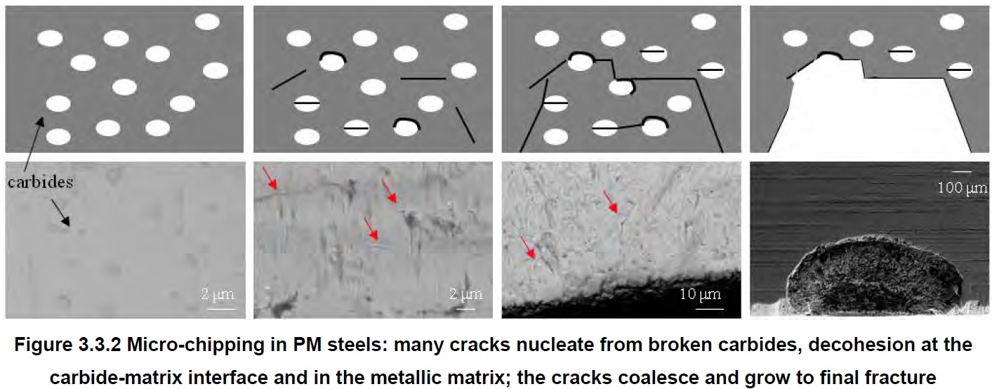
Micro-chipping of edges does not require the stress to reach the level of catastrophic growth of cracks, but can occur through the initiation and growth of small cracks that link up and lead to fracture. Micrographs illustrating this can be seen here [7]:
This is exacerbated by the segregated carbide bands that are aligned along the rolling direction, which is what helps drive the crack propagation and linking parallel to the edge. While powder metallurgy steels have a lower degree of banding and segregated carbides, the short propagation of cracks can still occur, linking up the cracks to form a micro-chip [7]:
Micro-chipping is on a “micro” scale meaning that the chips are often not visible to the naked eye but require magnification. Therefore, micro-chipping is usually perceived as a loss of sharpness rather than obviously visible chipping. The short growth and linking up of carbides occurs through crack initiation at carbides and then growth through low-cycle fatigue.
Chipping
Chipping, as differentiated from micro-chipping, is on a more macroscopic scale and requires high stresses that exceed the fracture toughness, KC, of the steel to allow rapid propagation of large cracks. Therefore those types of chips occur either in a single high application of stress or a very small number of cyclic stresses. Avoiding these types of chips requires either a change in use, higher toughness by changing material or heat treatment, or change in edge geometry [17]:
Conclusions and Micro-chipped Knife Edge
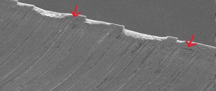
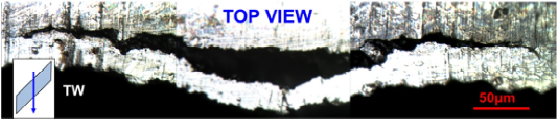
In 2007 Sandvik metallurgists sent me micrographs of several steels along with images of various damaged edges to demonstrate failure mechanisms of knives. They have low-res versions on their site [18]. I think it’s a good idea to analyze these to see if the mechanisms discussed in the rest of this article line up with our observations:
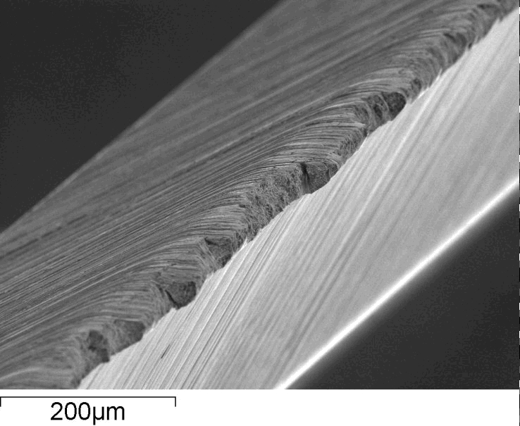

First of all I think it’s clear that there are scratches in the edge from sharpening which as described earlier can act as preferential sites for crack initiation. In the second image as marked with arrows you can see the cracks that formed parallel to the edge as shown in this article. And the chips themselves are longer than they are tall perhaps indicating that the cracks formed by cracks linking up along the rolling direction. Therefore I would say that mechanisms of micro-chipping and chipping are all aligning along similar lines from multiple sources. Chipping is controlled by steel toughness though there are different mechanisms in play. Micro-chipping is more controlled by low-cycle fatigue and linking up of cracks that form along carbides. Chipping is on a more macro scale and the stress must reach the fracture toughness of the steel. Larger carbides, a greater volume of carbides, and segregation of carbides all increase susceptibility to chipping. Hardness, grain size, and retained austenite all affect toughness and therefore the crack formation, propagation, and chipping and micro-chipping in addition to the carbides.
[1] https://scienceofsharp.wordpress.com/2015/10/30/burr-removal-part-1/
[2] https://www.twi-global.com/technical-knowledge/faqs/faq-what-is-charpy-testing/
[3] Novotny, Paul M. “Toughness index for alloy comparisons.” Advanced materials & processes 165, no. 5 (2007): 29-31.
[4] Bannister, A. C. “Determination of fracture toughness from Charpy impact energy: procedure and validation.” British Steel plc (1998).
[5] Lou, Bingzhe, and B. L. Averbach. “The effects of heat treatment on fracture toughness and fatigue crack growth Rates in 440C and BG42 steels.” Metallurgical Transactions A14, no. 9 (1983): 1899-1906.
[6] https://www.sharcnet.ca/Software/Hyperworks/help/hwsolvers/hwsolvers.htm?fpm_en_strain.htm
[7] Picas Anfruns, Ingrid. “Mechanical behaviour of tools for shearing Ultra High-Strength Steels: influence of the microstructure on fracture and fatigue micro-mechanisms of tool steels and evaluation of micro-mechanical damage in tools.” (2012).
[8] Hertzberg, Richard W. “Deformation and fracture mechanics of engineering materials.” (1989).
[9] Randelius, Mats. “Influence of microstructure on fatigue and ductility properties of tool steels.” PhD diss., KTH, 2008.
[10] Blaha, J., C. Krempaszky, E. A. Werner, and W. Liebfahrt. “Carbide distribution effects in cold work tool steels.” In 6th International Tooling Conference, pp. 289-298. Karlstadt University, Schweden, 2002.
[11] Jurči, Peter, and Ivo Dlouhý. “Fracture Behaviour of P/M Cr-V Ledeburitic Steel with Different Surface Roughness.” Materials Engineering 18, no. 2 (2011): 36-43.
[12] Horton, S. A., and H. C. Child. “Relationship between structure and fracture behaviour in 6W–5Mo–2V type high-speed steel.” Metals Technology 10, no. 1 (1983): 245-256.
[13] https://www.uddeholm.com/files/PB_Uddeholm_vanadis_4_extra_english.pdf
[14] Hilditch, Timothy B., Ilana B. Timokhina, Leigh T. Robertson, Elena V. Pereloma, and Peter D. Hodgson. “Cyclic deformation of advanced high-strength steels: mechanical behavior and microstructural analysis.” Metallurgical and Materials Transactions A 40, no. 2 (2009): 342-353.
[15] Wang, Xinchen. Fatigue behavior and microstructure examination of AISI D2 trim dies. Wayne State University, 2013.
[16] Schneider, R., A. Schulz, C. Bertrand, Alfred Kulmburg, A. Oldewurtel, V. Uhlenwinkel, and D. Viale. “The performance of spray-formed tool steels in comparison to conventional route material.” In Proc. 6th Int. Tooling Conf, pp. 1111-1124. 2002.
[17] https://www.quora.com/How-does-a-swordsmith-repair-a-chipped-blade
[18] https://www.materials.sandvik/en/products/strip-steel/strip-products/knife-steel/knife-steel-knowledge/
Great article interesting to see how non-homogeneity in steel can help overcome fracturing… interesting the balance between crack initiation and propagation… which i recently started seeing with aebl and some or other high carbide steel at same hardness 63 – both perform at fine edges, but they seem to fail diferently…
In what different way do they fail?
Aebl rolls and maybe chips but you can feel the edge roll /roughness if you drag a fingernail sideways. whilst the k490 gets extremely tiny chips – chips you strop out… but you dont feel it from the side k490 then feels a bit sharper than aebl but it is probably not very objective…
Both at rc63 and below 10dps
Dear Larrin,
I am looking at the chart fracture toughness vs hardness. Each curve (5, 10 and 13% carbide) are going toward lower K1C when HRc increases. This can only go with the size and distribution of carbides as percentage is constant. There should be fine (and plenty of it) particles on one side (the hard side?) vs a few big chunks of carbides. But if fine particles are on the hard side, it should mean higher K1C.
I cannot give it any sense. Are we talking about primary and secondary carbides together? Please help
The hardness of the steel doesn’t control the size of the carbides.
The fact that interparticle spacing is lowered by PM and contributes
to less difficult crack propagation throught the material
actually means that the lower grit edge sharpening finishes
on high wear pm steels which are often praised for an aggresive edge
on fibre materials perhaps it can be detrimental for edge/tool durabilty
by a greater amount than on the alloys with less carbide that would
exhibit much higher toughness at the same time.
This is going to be a tough one.
Let me quote:
” Larger carbides, a greater volume of carbides, and segregation of carbides all increase susceptibility to chipping. Hardness, grain size, and retained austenite all affect toughness and therefore the crack formation, propagation, and chipping and micro-chipping in addition to the carbides. ”
Thank you for that!
Now, I have a question that probably cannot be answered (too many variables) but I’ll ask anyway:
Comparing different knife steels, lets say 12c27m (almost no carbides as far as I understand) vs 13c27 (fine carbides) vs anything with larger carbides (maybe Super Blue), which edge would be tougher?
Because 12c27m cannot be hardened beyond 59HRC, but it has almost no carbides. 13c27 can be hardened to 63 (even though no commercial knife maker is doing it) but it does have carbides that compromise toughness. Super Blue can likewise go to 64HRC, but it does have large carbides.
I’m interested from the perspective of kitchen knives, so stress happens as impact into a cutting board and edge angles are fairly low (10-15DPS).
In short, would a lower hardness steel with no carbides be tougher against impacts than a higher hardness steel with carbides (small or large)???
Thank you, again!
Hi Peter,
That answer is easy: maybe.
Lower hardness with no carbides would mean higher toughness but of course lower strength. This becomes a question of “failure mode.” If the failure mode transitions from chipping to rolling (from low strength) then it may well be a harder, less tough steel that sees less damage. Edge geometry, hardness, corrosion resistance, wear resistance, and toughness all have some interplay depending on the application.
Late to the party, but maybe someone is still watching:
Given what you summarized in “Importance of Orientation”, does that mean that knifes not using a pointed tip (like a Nakiri) are produced in transverse direction, whereas all other knifes are produced using steel in rolling direction? A short googling didn’t really produce results.
It’s more likely they produce them the same as the others.
Thanks for your reply. Would it make any sense, though? Or is it a straight “well, it’s complicated…”
If I understand correctly, it is mostly that steel bar stock is produced by rolling out long strips of standard widths and thicknesses. While structural steel is commonly made in sizes large enough that you could cut knives lengthwise from the width of a piece, knife steels are not – they are manufactured in much smaller quantities, and it would also be a challenge to do the extra cutting steps that this would require with some of the steels used – especially the ones containing more carbides and having a higher level of hardness, which would actually benefit the most.
When the steel being produced is wider, that doesn’t mean that the impurities and carbide stringers are also further apart. And if they were that wouldn’t mean they were far enough apart not to matter anymore for knives being cut out in the transverse direction.
As a side note, the two micrographs at 100 and 200 micro m seem to show burred edges.
During the sharpening process, for the edge angle to decrease near the edge, the edge has to be deformed, probably back and forth through stropping or honing, which might weaken the edge.
Just saying these might be micrographs of freashly sharpened blades, not even damaged through use.
Those edges were intentionally chipped for the photographs as I understand it.
They reminded of me of some these (less dramatic) burr micrographs: https://scienceofsharp.com/2015/01/11/what-is-a-burr/
I thought it was interesting since you were describing the crack initiation from the honing scratches and I was wondering if the honing process might have also played another role through edge fatigue. I might very well be wrong!
In any case, very interesting article and impressive work! Thank you!