Update 7/6/2018: Since the writing of the original article I found some excellent micrographs that show austenitization very well and serve as a good supplement to the schematic diagrams. Go to the bottom of the article to see them.
During heat treating you’ve got to heat the steel up to form austenite, dissolve some carbon and alloy in solution, and rapidly quench to form martensite.
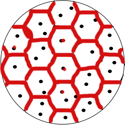
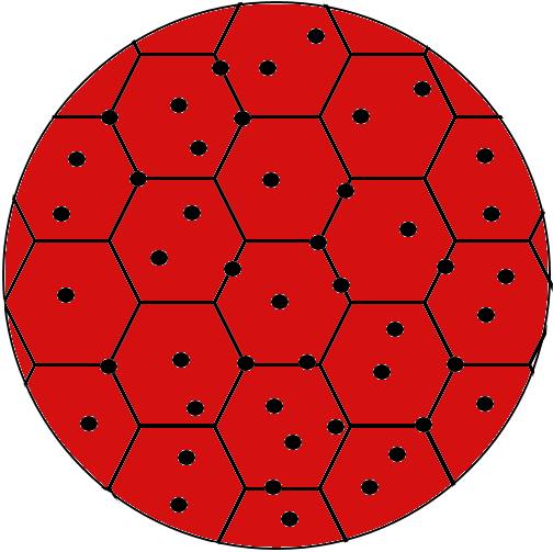
If we assume we start with an annealed microstructure of ferrite and carbides we get something that looks like the following schematic:
Here we have an idealized grain structure made up of boundaries and the black circles represent the carbides which are a very hard intermetallic made up of carbon and other elements such as iron, chromium, vanadium, etc.
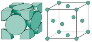
On a finer scale the ferrite is a “Body Centered Cubic” microstructure which can be represented by the following “unit cell” or the smallest possible unit which can describe the arrangement of atoms:
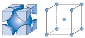
A BCC microstructure has an atom on each corner and one atom in the center, and is “cubic” or forming a perfect cube. In the unit cell each corner is repented by 1/8th of an atom which is shared by the surrounding unit cells, so when all of the unit cells are stacked together you get a complete BCC structure:
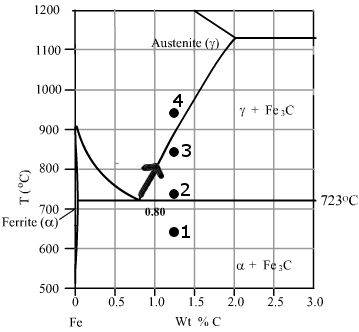
This microstructure represents “Point 1” on the following phase diagram [1]:
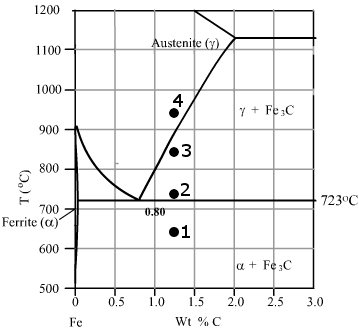
If we heat the steel into the austenite + carbide region at point two the steel starts to transform to austenite rather than ferrite, first by nucleating austenite at carbides and at grain boundaries. Ferrite is very low carbon (<0.02%) but austenite requires much more carbon to be stable, something close to the eutectoid composition (~0.77%C). So the austenite nucleates on carbides since they are the source of carbon available. The carbides have to dissolve somewhat to feed carbon to the growing austenite. The carbides along grain boundaries are even more favorable because the grain boundaries are high energy areas, the steel “wants” to minimize its energy so the elimination of these boundaries is energetically favorable.

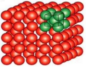
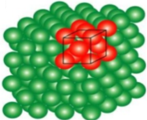
Austenite is a “Face Centered Cubic” microstructure, which again is a represented by a perfect cube with an atom on each corner, but instead of an atom at the center, an atom is present on each “face” of the cube, where half of an atom is in each unit cell:
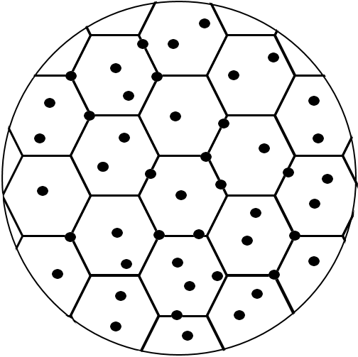
After the austenite nucleates it starts to grow, replacing the ferrite with austenite and carbon is continuously diffusing to feed the growth of the austenite. Grain boundaries allow more rapid diffusion so that is the first place that austenite grows:

Once the boundaries are covered in austenite then it will continue to grow inward into the ferrite until the microstructure is made up of austenite and carbides:
With increasing temperature from that point the carbides dissolve leading to a smaller amount of carbide and the carbon content of the austenite increases corresponding to the line on the phase diagram indicated by the arrow:
This doesn’t happen instantaneously, however, as it is limited by the rate of diffusion. Here is a model of carbon in solution with time for 52100 [2]:
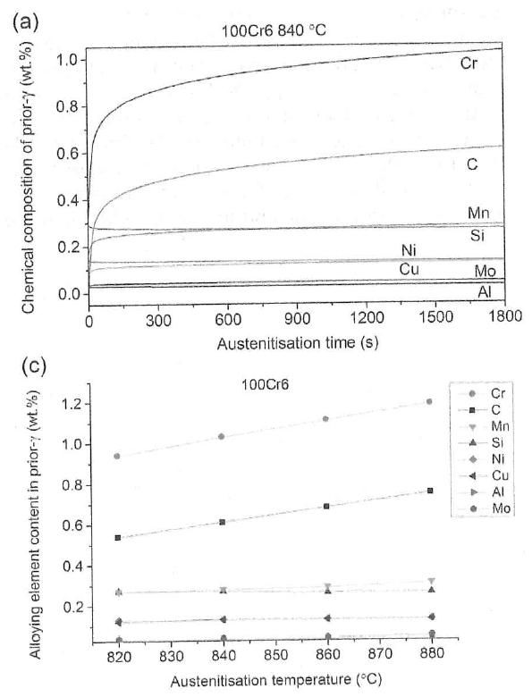
As the carbides dissolve the carbon and chromium in solution are increased as you can see in the chart.
While the carbides do help suppress grain growth by “pinning” boundaries, the grains also continuously grow as the temperature increases or the time at temperature increases. Again, the boundaries are high energy areas that the steel would like to eliminate, and one way it does that is by growing the grains. The higher the temperature the faster diffusion is so that grain growth is more rapid. As more carbides dissolve there are fewer carbides to pin the grain boundaries which also leads to more rapid growth, eventually all of the carbides are dissolved and point “4” is reached, where grain growth occurs more rapidly. This is a great video which illustrates grain growth [3]:
You can see that the larger grains consume the smaller grains. This continues nearly indefinitely though a single crystal structure is never reached because, in part, of the constraints of the outer surfaces of the material.
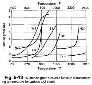
The type and distribution of carbides in tool steels affects the temperature at which grain growth occurs more rapidly, as can be seen in this chart for different tool steels [4]:
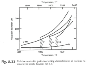
For low alloy steels the carbides dissolve at relatively low temperatures, but AlN are present in aluminum-killed steels to help suppress grain growth. Of course, vanadium additions are somewhat common to help suppress grain growth in steels such as W2 from the formation of a fine array of vanadium carbides. However, niobium and titanium can be even more effective for preventing grain growth due to the stability of NbC and TiC at very high temperatures [5]:
So grain size, carbon in solution, and carbide volume are controlled by the temperature and time at the chosen austenitizing temperature. One important aspect is the amount of other alloys in solution for sufficient hardenability, or elements like chromium for stainless steels. Sufficient chromium must dissolve in the austenite prior to quenching to martensite to ensure that good corrosion resistance is achieved. So there is a balance in choosing an austenitizing temperature to get the right amount of carbon and alloy is in solution, the correct carbide volume has been achieved, and excess grain growth has been avoided.
In the next post I will start to write about more practical aspects of austenitizing and how it affects final properties.
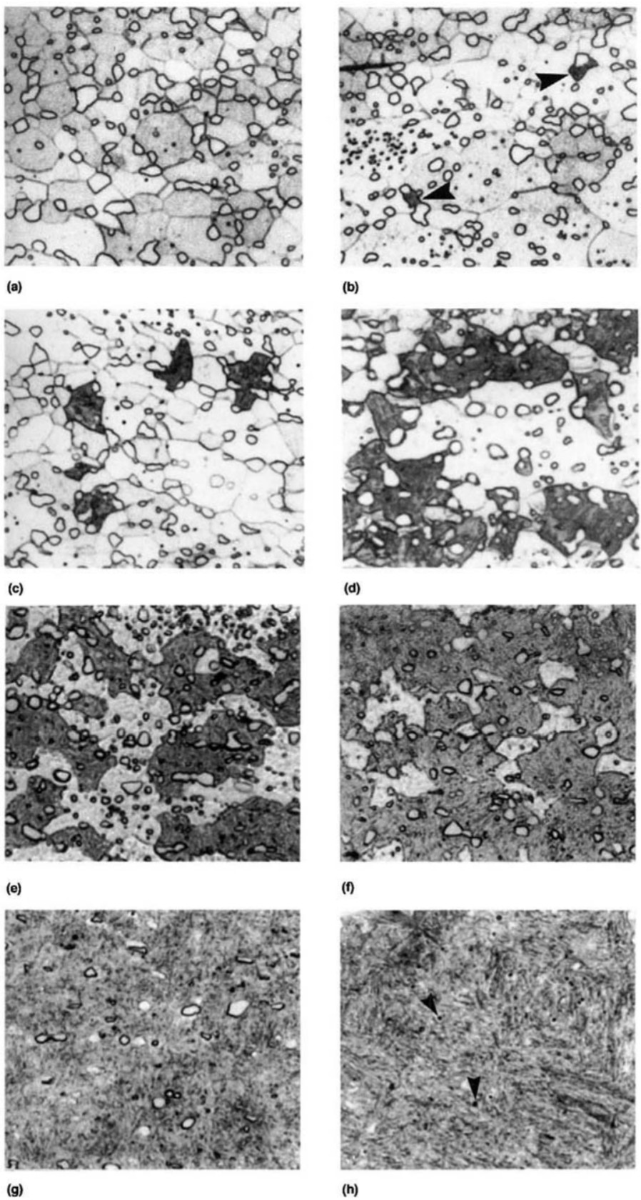
Update 7/6/2018: These micrographs are of 1080 steel [6] with increasing time at austenitizing temperature, where the dark austenite replaces the ferrite. The last two micrographs also show the dissolution of the carbides where carbides are seen in (g) but they are largely removed in (h). The steel was held at 730°C (1346°F) for 9s (a), 9.5s (b), 10s (c), 11s (d), 12s (e), 60s (f), 300s (g), and 900s (h). You can see that the formation of austenite is relatively rapid, but that the dissolution of carbides takes longer.
[1] Modified from this page: http://www-g.eng.cam.ac.uk/mmg/teaching/typd/addenda/eutectoidreaction1.html
[2] Cui, Wen, David San-Martín, and Pedro EJ Rivera-Díaz-del-Castillo. “Towards efficient microstructural design and hardness prediction of bearing steels—An integrated experimental and numerical study.” Materials & Design 133 (2017): 464-475.
[3] https://www.youtube.com/watch?v=J_2FdkRqmCA
[4] Roberts, George Adam, Richard Kennedy, and George Krauss. Tool steels. ASM international, 1998.
[5] Repas, P. E. “Microalloyed HSLA Steels.” Proceedings of Microalloying. 1988.
[6] Samuels, Leonard Ernest. Light microscopy of carbon steels. Asm International, 1999.
Good , Excellent i like
Likewise
Are all the atoms that make up each cubic iron? Or are some of them carbon(or other elements)? Like when we say “in solution” does that mean “part of the face centered cubic”?
There are substitutional and interstitial elements. Substitional elements replace an iron atom, these include manganese, chromium, molybdenum, etc. Interstitial atoms sit between iron atoms and include carbon and nitrogen.